Free online calculator to compute voltage drop and energy losses in a wire
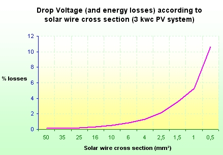
Losses in solar PV wires must be limited, DC losses in strings of solar panels, and AC losses at the output of inverters. A way to limit these losses is to minimize the voltage drop in cables. A drop voltage less than 1% is suitable and in any case it must not exceed 3%.
Save electricity : this free online calculator gives the AC and DC
Power, Voltage Drop, wire energy losses, resistive heating, for
three phase and single phase wiring.
Fill the yellow fields and press "calculate" buttons. Results are
displayed in green fields.
AC VOLTAGE DROP and ENERGY LOSSES CALCULATOR
DC VOLTAGE DROP and ENERGY LOSSES CALCULATOR
| DC POWER |
|---|
|
V A W
|
| DC Voltage Drop |
|---|
|
Wire size (mm2) : °C m V
|
| DC Energy losses |
|---|
|
W
%
|
HOW TO CALCULATE VOLTAGE DROP AND ENERGY LOSSES IN A WIRE?
VOLTAGE DROP
Voltage drop is given by the following formula :

U : Voltage of the DC or AC system (V)
This is phase-phase voltage for 3-phase system; phase-neutral voltage for single-phase system.
Example :
- For western European countries a 3-phase circuit will usually have a voltage of 400 V, and single-phase 230V.
- In North America, a typical three-phase system voltage is 208 volts and single phase voltage is 120 volts.
NB: for DC voltage drop in photovoltaic system, the voltage of the system is U = Umpp of one panel x number of panels in a serie.
ΔU : voltage drop in Volt (V)
b : length cable factor, b=2 for single phase wiring, b=1 for three-phased wiring.
ρ1 : resistivity in ohm.mm2/m of the material conductor for a given temperature. At 20 celcius degree °C the resistivity value is 0.017 for copper and 0.0265 for aluminium.
Note that resistivity increases with temperature. Resistivity of copper reaches around 0.023 ohm.mm2/m at 100 °C and resistivity of aluminium reaches around 0.037 ohm.mm2/m at 100 °C.
Usually for voltage drop calculation according to electrical standards it is the resistivity at 100°C that is used (for example NF C15-100).
ρ1 = ρ0*(1+alpha(T1-T0)), here ρ0 = resistivity at 20°C (T0) and alpha = Temperature coefficient per degree C and T1 = temperature of the cable.
T1 : Temperature of the cable (default value = 100°C).
Note that from experience, a wire with a correct sizing should not have an external temperature over 50°C, but it can correspond to an internal temperature of the material around 100°C.
L : simple length of the cable (distance between the source and the appliance), in meters (m).
S : cross section of the cable in mm2
Cos φ : power factor, Cos φ = 1 for pure resistive load, Cos φ< 1 for inductive charge, (usually 0.8).
λ : reactance per length unit (default value 0.00008 ohm/m)
Sin φ : sinus (acos(cos φ)).
Ib : current in Ampere (A)
NB : For DC circuit, cos φ=1, so sin φ=0.
Voltage drop in percent :
ΔU(%) = 100 x ΔU/U0
Where :
ΔU : voltage drop in V
U0 : voltage between phase and neutral (example : 230 V in 3-phase 400 V system)
ENERGY LOSSES
Energy losses in a cable is mainly due to resistive heating of the cable.
It is given by the following formula :
E = a x R x Ib²
Where :
E : energy losses in wires,
Watt (W)
a : number of line
coefficient, a=1 for single line, a = 3 for 3-phase circuit.
R : resistance of one active
line
Ib : current in Ampere (A)
R is given by the next formula :
R = b x ρ1 x L / S
b : length cable factor, b=2
for single phase wiring, b=1 for three-phased wiring.
ρ1 : resistivity of the
material conductor, 0.017 for copper and 0.0265 for aluminium (temperature of the wire of 20°C) in ohm.mm2/m. Resistivity of copper reaches around 0.023 ohm.mm2/m at 100 °C and resistivity of aluminium reaches around 0.037 ohm.mm2/m at 100 °C.
L : simple length of the cable
(distance between the source and the appliance), in meters (m).
S : cross section of the cable
in mm2
NB : for direct current the energy losses in percent is equal to the voltage drop in percent.


